Beyond the Digital Zone System
— by Russell Cottrell
The digital zone system
What is the zone system? Can it be applied to digital imaging? There has been a lot written about this subject in the past few years; but unfortunately, much of it is based on myths and misconceptions about what the zone system is all about. Many of these misconceptions arise because when Ansel Adams wrote about it, he was usually talking about its application to black-and-white negatives; and when using that medium, it is logical to use a ten- or eleven-zone system. But he also applied it to color and transparency materials, and he wrote an entire book about Polaroid Land Photography; and it is clear from his writings that not all photographic media use ten zones, and that dividing everything into ten zones is not the point of the zone system.
Ansel’s description of the zone system in a nutshell was, “relating subject luminances with print values.” We might today say “image values” because not all digital imaging is intended to be printed. And as Ansel consistently stated, the purpose of the zone system is to enable visualization. To apply the zone system to digital imaging, let us begin here.
Visualization
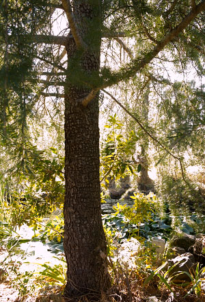
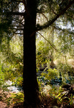
What is visualization? It is the ability to evaluate a scene and know ahead of time how one would like the resulting image to look. And there are choices to be made when visualizing any scene. Consider the following examples. The subject consists of a shaded backlit tree in front of a sunlit pond. For the first image, I visualized a luminous tree trunk and foreground with a brilliant background behind it. For the second, I “changed my mind” and visualized a full-scale sunlit background scene with the tree trunk in silhouette. Which image is “correct”? Which is “better”? It all depends on how one visualized the scene.
|
|
Subject luminances
  |
| Two ways of visualizing the same scene. Not all of these subject luminances can be recorded in a single image; a choice must be made. |
We refer to the amount of light reflected from a subject element as luminance. When a photographer looks at a scene, he or she sees a range of subject luminances which he or she intends to convert into image values. The eye responds to luminance logarithmically, and it is common to express luminance differences in units of powers of two, which I shall call stops. The range of luminances in any given environment may be huge, sometimes 20 stops (a factor of 220, or 1,048,576) or more. But no photographic medium can record such a large range in a single image; there is a limit to each medium’s dynamic range. Negative films, both color and black-and-white, can usually record a range of at least 12 stops (a factor of 4096). Transparency film can record much less. Digital media were formerly limited to small ranges as well, but are catching up to film due to ongoing improvements in technology.
We measure subject luminances with a light meter. Conventional light meters are based on the aperture and shutter speed combinations which determine the exposure of the medium to light. These combinations are properly referred to as exposure values; and each increment, or stop, results in a doubling or halving of the amount of light captured by the exposure.
The sensitivity of the medium to light is called its speed. Film and digital camera manufacturers publish a speed for each medium based on standards set by the International Organization for Standardization (ISO). Light meters couple the designated speed with the amount of light that they receive from the subject to indicate an exposure value.
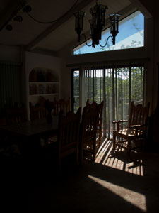
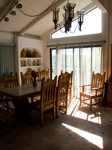
The photographer presumably knows what he or she is looking at, and has an idea of what subject elements should appear light or dark in the final image. The light meter, however, has no such idea. If the film or camera speed has been correctly determined, then metering a uniform subject and using the indicated exposure value to take the picture will result in an image value about halfway between black and white; the usual term for this is “middle gray,” but of course it may be a color. This applies to any subject, be it a coal bin or a snowdrift. Cameras generally have some sort of averaging meter built-in; it averages the entire scene and indicates an exposure that assumes that the overall luminance of the scene is a middle gray. However, this assumption is often not the case; and even when it is close, some bright or dark subject elements may fall outside the dynamic range of the medium, and so be overexposed or underexposed in the image.
Can the photographer exercise more control over the process? In the pre-zone-system days, photographers would “expose for the shadows.” One would meter what is intended to be a dark, textured object, such as black fabric. The meter, as usual, indicates an exposure that assumes that the subject is middle gray. Reducing the exposure by two stops will usually render the dark object as an acceptable dark value in the final image. This method works well with negatives, since with this medium, it is usually more important to prevent underexposure than overexposure. For digital imaging, where the reverse is true, it may make more sense to “expose to the right”; one meters something that is intended to be a light textured object, such as white cloth or a light stucco wall, and then increases the meter’s indicated exposure by two stops to raise it to an acceptable image value. Either of these methods can be successful, especially if one has tested one’s camera and subsequent processing, and made adjustments if necessary.
 |
 |
|
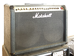
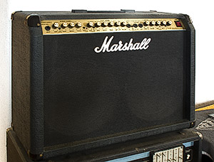
| Exposed according to the spot meter reading. Dark fabric is rendered middle gray. | Same, with exposure compensation of -2 dialed in. Images processed identically. | |
 |
 |
|
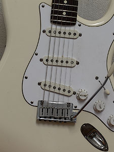
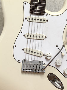
| Meter again indicates an exposure that results in middle gray. | Same, this time using exposure compensation of +2. | |
| Compare the second members of each of these pairs of images. You know that they are not the same color, but the light meter can’t tell the difference. | ||
Ansel Adams wanted to be able to exercise even more control over his medium, to “push it to the limits.” And, he wanted to be able to teach his method to others. So he came up with the idea of assigning subject luminances to exposure zones, and the zone system was born. When using the zone system, the exposure values that are recorded in the image are called zones. Since black-and-white negative film typically records a range of about ten zones, Ansel designated the exposure indicated by a light meter, corresponding to middle gray, as zone V. If one meters a subject and then increases the exposure by one stop, we call this placing the subject on zone VI. Increasing the exposure of the white Stratocaster above by two stops places it on zone VII. Similarly, reducing the exposure of the black fabric cover of the Marshall by two stops places it on zone III.
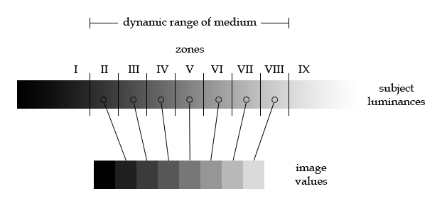
Image values
To “connect the dots” between subject luminances and image values, we will make a simple exposure series. It helps to set up your camera on a tripod in front of a suitable target. Any evenly-illuminated neutral smooth matte surface will do. Be sure that the lighting remains even, with no reflections or shadows. You will probably want to avoid long exposures, one second or more, as some cameras suffer from a lot of long-exposure noise. Also, to the extent that you are able, be sure that no in-camera processing is being performed. The camera’s ISO setting is important; if you intend to use different ISO settings, you will have to make separate exposure series at each ISO.
Meter the surface; the indicated exposure places it on zone V. Increasing the exposure by one stop places it on zone VI; decreasing it similarly places it on zone IV. Make a series of exposures running from zones -I to IX. Then make a “zone ruler” from the resulting images that runs from pure black to pure white. The zone ruler below is typical of digital cameras whose output images are .jpg or .tif files. As you can see, if you have a decent and well-adjusted monitor, the first hint of shadow exposure occurs at zone I; full detail probably begins at zone II. And zone VII is the last zone to record highlight detail; everything above it will be pure white in the image.

|
||||||||
| O | I | II | III | IV | V | VI | VII | VIII |
Your results may differ from the above. For example, your zone I may still be pure black, or your zone VIII may not yet be pure white. There may be ways to adjust for this; some cameras have a means of “tweaking” the exposure to bring it in line with a desired standard, such as keeping the lightest highlight detail on zone VII. Or, you may simply adopt a permanently-dialed-in exposure compensation. (With digital cameras, changing the camera’s actual ISO is not the way to do it.) You may even want to make your zone ruler exposures in 1/2- or 1/3-stop increments so it has finer steps, especially at the high end. But none of this is required; the point is that now you know how your camera turns your subject luminances into your image values.
This knowledge enables you to visualize an image, and then make an exposure which records the subject luminances as the image values that you want. In other words, it enables you to use the zone system.
The zone system
Returning to the example of the tree and pond above: visualizing the first image, I wanted the tree trunk to appear illuminated, but not quite middle gray, so I placed it on zone IV. Using the camera’s built-in meter, I could have either metered the tree trunk and then reduced the indicated exposure by one stop to place it on zone IV, or I could have simply metered it with an exposure compensation of -1 dialed in. What I actually did was meter it with the Pentax V spotmeter. Its exposure value was 7; placing it on zone IV at ISO 200 indicated an exposure of 1/4 sec at f/11. The metered value of the grass at the lower left was 14; it thus fell on zone XI, and, as expected, appears pure white in the image.
For the second image, I placed the grass on zone VI so it would be a light value with plenty of detail; exposure was 1/125 sec at f/11. The tree trunk fell on zone -1, and is recorded in silhouette.
Note that, in our discussion of digital imaging above, at no time did dividing everything into ten zones have anything to do with the zone system. Zones are the exposure values that are recorded by your camera in your images, and the number of zones depends on your camera, and other factors such as perhaps the ISO setting, and whether or not you are using RAW images (more about that later). A cursory and incomplete understanding of the zone system will keep you from knowing what is actually happening when you take a photograph, and is likely to lead to incorrect results if you obey black-and-white negative clichés such as, “place textured highlights on zone VIII.”
What comes next?
The above was a beginner’s introduction to the zone system; an avid practitioner goes deeper. Next comes calibration of one’s system in detail, from start to finish. Having done that, one is able to exercise even more control over the process and final result, with the goal of more creativity and expression in one’s images. Another insidious zone system myth is that it encourages slavish imitation; if you really understand it, the zone system unleashes your potential.
Summary—an overview of the workflow described below.
Workflow—a detailed application of the zone system to a Nikon D700 and a Leaf Aptus-II 5 digital back. Walks you through the steps of system calibration from camera to printer, then explores even more advanced topics following the example of Phil Davis in Beyond the Zone System.
Myths, Definitions, Approach—an attempt at a formal analysis of the underlying principles of the zone system, quoting liberally from the works of Ansel Adams and Minor White, ending with a general approach to applying the zone system to any photographic media. Much of the current page was condensed from this section.
2704